The Acoustic Paradox of Modern Grand Ballrooms
Grand ballrooms in contemporary luxury hotels and convention centers are architectural marvels: column-free footprints spanning 800 to 2,500 square meters, ceiling heights hovering between 6 and 9 meters, and modular partition walls designed to split the space into multiple configurations.
While the absence of load-bearing pillars creates unobstructed sightlines for event guests, it strips the acoustic engineer of convenient mounting locations. To compound the challenge, these spaces feature highly reflective boundary materials: polished marble borders, large mirror panels, floor-to-ceiling glass, and metal ceiling tracks.
The most common engineering mistake in these spaces is specifying a massive left-right line array flanking the stage. While line arrays excel in arenas and outdoor festivals where deep throw and narrow vertical pattern control are mandatory, deploying them in a 7-meter-tall ballroom creates severe acoustic problems:
- Excessive Front-to-Back SPL Discrepancy: Blasting the rear tables from the front proscenium subjects the VIP tables in the first five rows to painful levels (often exceeding 95 dBA), while rear attendees struggle to understand speech through diffuse room reflections.
- Excitation of the Reverberant Field: Wide horizontal directivity colliding with side glass and perimeter walls energizes the room’s late reflections, driving the Speech Transmission Index (STI) below acceptable corporate standards (typically target STI $\ge$ 0.60).
- Visual Obstruction: Interior designers and event planners consistently object to large suspended array hangs that block projection screens, ambient chandeliers, and sightlines to scenic stage elements.
The true solution lies in decoupling SPL generation from a single physical point by deploying a distributed point-source topology anchored by precision-aligned delay fills.
Understanding the Haas Effect in Distributed Audio Design
The core physics governing delayed fill systems rests on psychoacoustics—specifically the Haas Effect (also known as the Precedence Effect).
Human hearing determines sound direction based on the first arriving wavefront (within 1 ms of arrival). If a secondary, identical sound arrives between 5 ms and 30 ms after the primary sound, the human brain integrates both acoustic events into a single perceived sound while localizing the source entirely to the first-arriving wave—provided the delayed speaker is not more than 10 dB louder than the direct sound.
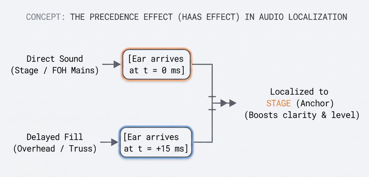
In a grand ballroom, our primary stage speakers establish the acoustic anchor point. As attendees move further down the hall, the direct acoustic energy from the stage drops naturally due to distance attenuation ($6\text{ dB}$ per doubling of distance in free space, roughly $4\text{ dB}$ to $5\text{ dB}$ in enclosed reverberant rooms).
Before direct sound drops below the ambient noise floor or degrades into the room’s reverberant tail, a delay speaker overhead or along the perimeter introduces a fresh wavefront. Because we electronically delay this secondary speaker to fire just after the stage sound passes overhead, attendees perceive the sound as originating naturally from the presenter on stage, even though up to 70% of the local acoustic energy entering their ears comes from the speaker directly above them.
Precision Delay Time Calibration and Step-by-Step Tuning
Delay alignment is never a matter of guesswork or rough room estimates. It requires calculating acoustic transit times based on ambient room conditions, followed by dual-channel FFT software verification (e.g., Smaart, Systune).
1. Calculating Physical Speed of Sound
Sound velocity ($c$) fluctuates with ambient air temperature:
$c \approx 331.3 + (0.606 \times T)$
Where $T$ is temperature in Celsius. In a climate-controlled ballroom running at $22^\circ\text{C}$:
$c \approx 331.3 + (0.606 \times 22) \approx 344.6\text{ m/s}$
This translates to an acoustic latency of approximately $2.90\text{ ms}$ per meter ($0.884\text{ ms}$ per foot).
2. The Baseline Delay Formula
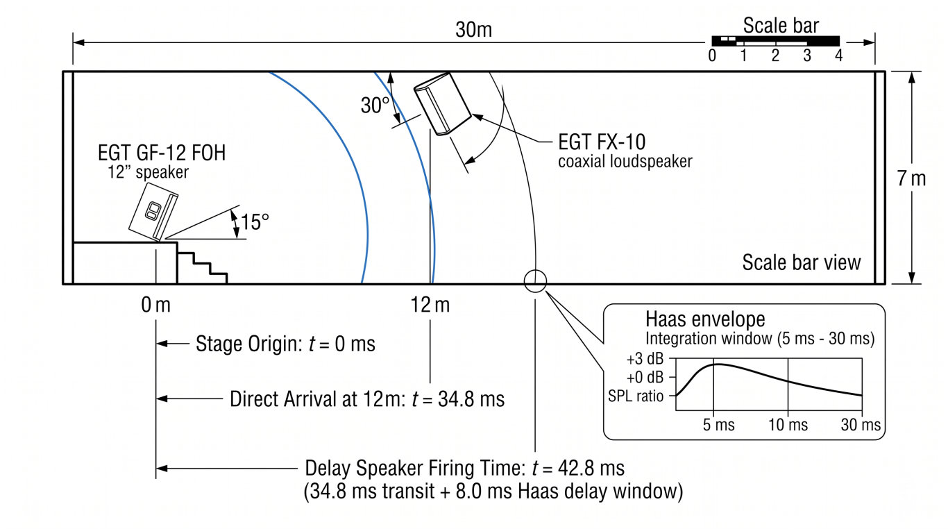
The base physical transit delay ($t_{\text{phys}}$) required for a delay speaker positioned at distance $d_{\text{delay}}$ from the main front-of-house (FOH) speakers is:
$t_{\text{phys}}\text{ (ms)} = \left( \frac{d_{\text{delay}}\text{ (meters)}}{c} \right) \times 1000$
To ensure the listener’s brain remains locked onto the stage, we inject a Haas bias delay ($\Delta t_{\text{Haas}}$) of $5\text{ to }15\text{ ms}$:
$t_{\text{total}} = t_{\text{phys}} + \Delta t_{\text{Haas}} + t_{\text{latency\_offset}}$
(Note: $t_{\text{latency\_offset}}$ accounts for any internal DSP conversion latency differences between separate processor paths, typically $1.0\text{ to }2.5\text{ ms}$.)
3. Field Calibration Sequence
- Solo the FOH Main Speaker: Place the measurement microphone directly on the acoustic axis of Delay Row 1 at seated ear height ($1.2\text{ meters}$). Capture the impulse response (IR) peak of the direct arrival from the main proscenium loudspeaker.
- Solo the Delay Speaker: Mute the main speaker, unmute the delay speaker, and run an impulse response measurement. Note the arrival time of its direct peak.
- Coarse Delay Setting: Set the DSP channel delay on the fill speaker so its impulse peak lands between $5\text{ ms}$ and $10\text{ ms}$ after the FOH main peak.
- Phase Alignment Across the Crossover Band: View the phase trace in the overlap zone (typically $500\text{ Hz}$ to $2\text{ kHz}$). Adjust delay in $0.2\text{ ms}$ increments until the phase slopes of both sources track parallel through the critical mid-band. This eliminates the acoustic comb filtering that causes hollow, boxy speech.
- Level Matching: Turn both speakers on. Adjust the delay speaker output so it matches the direct sound level from the stage or sits no more than $2\text{ to }3\text{ dB}$ higher. If the fill speaker exceeds the direct arrival by more than $6\text{ dB}$, the precedence illusion collapses, and the listener immediately localizes the sound to the ceiling.
Hardware Selection: Matching Directivity and Amplification
In high-end hospitality venues, point-source loudspeakers must satisfy two strict criteria: broad, seamless high-frequency dispersion without destructive off-axis phase cancellations, and clean mechanical integration.
| System Position | Recommended Hardware | Configuration Specs | Key Engineering Role |
|---|---|---|---|
| Front-of-House Proscenium Mains | EGT GF-12 Point-Source Loudspeaker | 12” LF (305mm driver), 1.75” HF (44mm coil), 400W RMS / 1600W Peak, $53\text{ Hz} - 18\text{ kHz}$, $126\text{ dB}$ Max SPL | Flanking the primary stage. Delivers high acoustic energy and punch across the primary front seating plane with a rigid birch plywood enclosure . |
| Zone 1 & Zone 2 Delay Fills | EGT FX-10 Coaxial Conference Speaker | 10” Woofer (254mm) + 34mm HF Coaxial Driver, 200W RMS, Birch Plywood, Conical Dispersion, $119\text{ dB}$ Max SPL | Ceiling/truss suspended via dedicated U-brackets . True point-source coaxial design prevents horizontal/vertical lobing in overlap zones . |
| Multi-Zone Amplification | EGT AK4600 4-Channel Power Amplifier | Class-H architecture, Toroidal PSU, $4 \times 600\text{W} \text{ @ } 8\Omega$, Damping Factor $>230$, THD $<0.05\%$ | Drives Left Main, Right Main, Delay Row 1, and Delay Row 2 on discrete amplifier channels from a single $2\text{U}$ chassis . |
Why Coaxial Point Sources Are Critical for Delay Fills
Standard two-way speakers with separate woofers and horns suffer from acoustic displacement (the acoustic centers of the HF and LF drivers are physically separated by several inches). When you tilt a standard two-way speaker downward from a ballroom ceiling truss, off-axis listeners experience comb filtering in the crossover region ($1.5\text{ kHz} - 2.5\text{ kHz}$) due to differential path lengths from the two drivers.
Using a dedicated coaxial design like the EGT FX-10 eliminates this issue . Because the high-frequency compression driver fires directly through the center of the 10-inch low-frequency cone , the acoustic centers are aligned along the same axis. The resulting conical dispersion provides uniform, symmetrical off-axis behavior whether hung horizontally, vertically, or angled downward on a truss mount.
Critical Field Traps and Engineering Gotchas
- The “Ruler and Tape Measure” Fallacy: Never dial in DSP delays using physical room measurements alone. While measuring $18\text{ meters}$ gives you a theoretical $52.2\text{ ms}$ transit time, it ignores the internal processing latency of upstream digital mixing consoles, Dante transport buffers, and the FIR/IIR filter group delays within the DSP unit itself. Always verify with an impulse response measurement.
- Frequency Clutter in the Low-Mids: Delayed speakers are deployed to recover intelligibility ($1\text{ kHz} - 6\text{ kHz}$), not to reproduce heavy low-frequency energy. Running full-range delay fills down to $60\text{ Hz}$ floods the room with unnecessary omnidirectional bass, creating mud. Always engage a high-pass filter (HPF) on delayed fill channels around $90\text{ Hz} - 110\text{ Hz}$ (24 dB/oct Linkwitz-Riley) to prevent low-frequency build-up in room modes.
- The Guest Thermal Shift: Ballrooms are typically tuned in the afternoon when the room is empty and chilly ($20^\circ\text{C}$). By 8:00 PM, 600 dining guests have filled the room, bringing body heat, banquet warmers, and lighting heat that push room temperatures to $26^\circ\text{C}$. This temperature swing increases sound velocity from $343\text{ m/s}$ to $347\text{ m/s}$. On a long 30-meter delay throw, this shifts acoustic arrival by roughly $1\text{ ms}$. Keep your Haas offset comfortably around $8\text{ to }12\text{ ms}$—setting it too close to the $2\text{ ms}$ margin risks letting temperature shifts push the delay speaker ahead of the direct sound, inverting localization.
System Architecture Blueprint
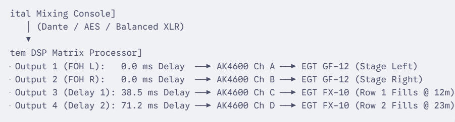
By engineering an intentional delay matrix, you reduce the required acoustic output from any single enclosure, keep direct-to-reverberant sound ratios well above critical distance thresholds, and maintain the aesthetic integrity of high-end corporate ballrooms.