Introduction
There was a time when walking into a festival front-of-house or amp compound meant encountering towering steel racks packed with massive, 4RU Class-AB and Class-H iron beasts. They were brutally reliable and musically transparent, but they were also backbreaking, generated staggering thermal loads (BTUs), and pulled punishing current draw from field generators.
When early switch-mode Class-D amplifiers first entered touring rigs, seasoned engineers were rightfully skeptical. The first generations suffered from coarse pulse-width modulation (PWM), dead-time crossover distortion, switching artifacts in the upper registers, and severe output filter interactions with dynamic loudspeaker impedances.
Over the past decade, that landscape has fundamentally transformed. Breakthroughs in high-speed switching devices, closed-loop feedback topologies, and switch-mode power supplies (SMPS) with active Power Factor Correction (PFC) have elevated Class-D from a lightweight compromise to the undisputed standard of touring-grade sound reinforcement. Paired with integrated DSP within active loudspeaker cabinets, Class-D does not merely match legacy analog iron—it enables sustained sound pressure levels and transient precision that passive systems simply cannot replicate.
Core Technical Analysis: The Engineering Leaps Behind Modern Class-D
To understand why modern Class-D dominates today’s high-output sound reinforcement, we must examine the physical bottlenecks of traditional amplification: conduction losses, switching speed limitations, and passive filter interactions.
1. Wide-Bandgap Semiconductors (GaN and SiC)
Early Class-D modules relied on silicon MOSFETs with finite switching speeds. To prevent shoot-through currents (where high-side and low-side switches momentarily conduct simultaneously), designers were forced to introduce “dead time.” This dead time was the primary culprit behind harsh upper-midrange odd-order harmonics.
The integration of Gallium Nitride (GaN) and Silicon Carbide (SiC) switches has slashed gate charge and output capacitance by orders of magnitude. GaN devices switch in nanoseconds rather than microseconds, operating at carrier frequencies well beyond 400 kHz to 1 MHz. This allows engineers to reduce dead time to near zero, eliminating the graininess of early designs and delivering an ultra-low total harmonic distortion (THD+N) profile comparable to studio-grade Class-A/AB topologies.
2. Post-Filter Feedback (PFFB) Topologies
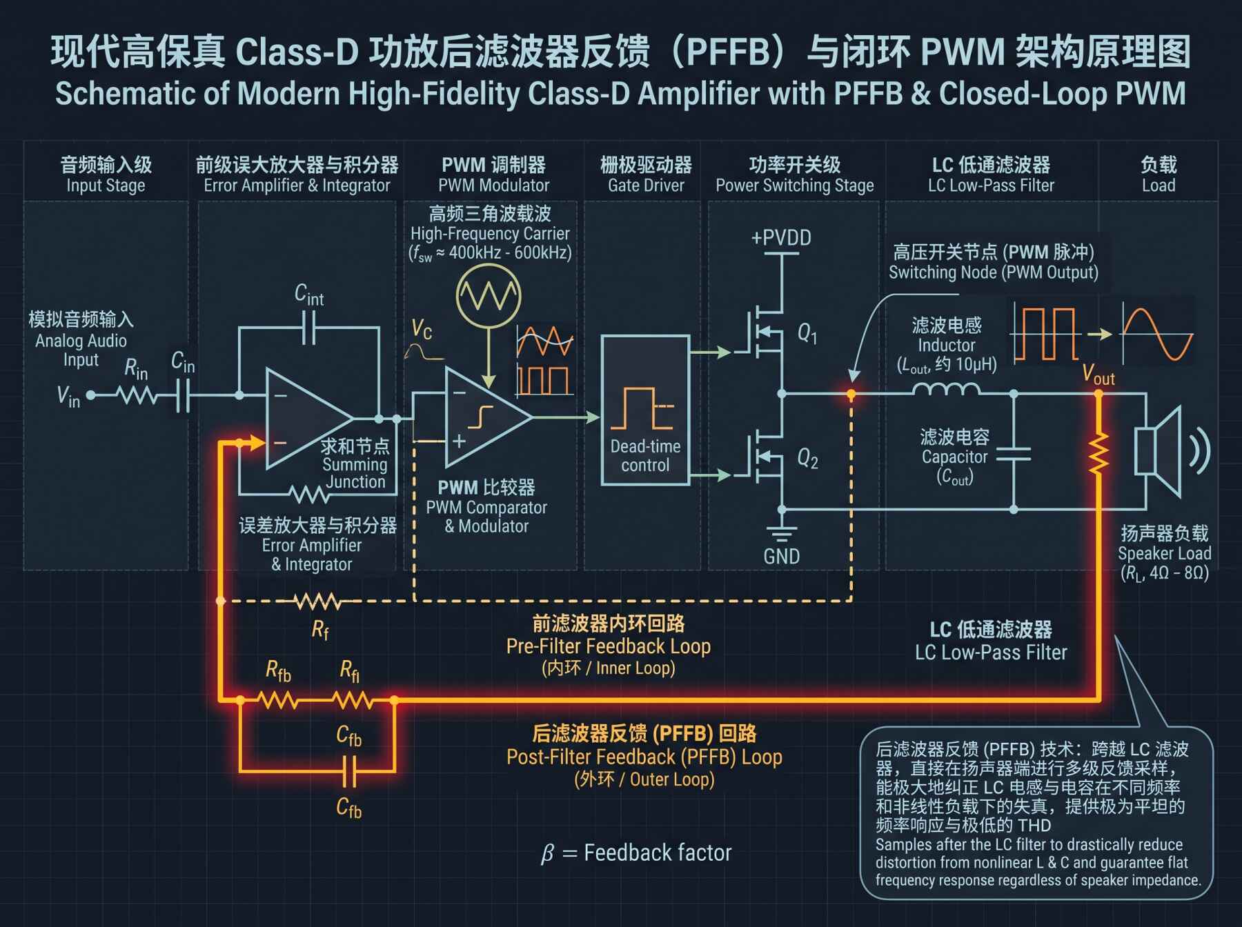
Class-D amplifiers require a low-pass output LC filter (inductor-capacitor) to strip away the high-frequency PWM carrier wave before the signal reaches the speaker terminals. In early open-loop or pre-filter feedback architectures, the impedance of this LC filter interacted directly with the reactive, frequency-dependent impedance of the loudspeaker cone. A speaker with an impedance peak at 2 kHz would experience an uncontrolled amplitude peak; an impedance dip at 10 kHz would cause premature roll-off.
Modern touring modules employ sophisticated Post-Filter Feedback (PFFB) networks. By tapping the error-correction feedback loop directly from the speaker terminals after the LC filter, the amplifier compensates for filter non-linearities and dynamic impedance swings in real time. The resulting frequency response remains ruler-flat whether driving a 16-ohm high-frequency compression driver or an inductive 2-ohm subwoofer array.
3. Regulated SMPS with Active Power Factor Correction (PFC)
An amplifier cannot produce clean acoustic power without a resilient power reservoir. Traditional linear power supplies sagged severely when subwoofers hit sustained 40 Hz low notes. Modern tour-grade platforms utilize regulated switch-mode power supplies paired with active PFC. Active PFC continuously shapes the input current waveform to match the mains voltage wave, maintaining a power factor close to 0.99. This allows amplifiers to pull clean, continuous energy from 85V up to 265V AC without suffering rail collapse during high-SPL festival transients.
| Performance Attribute | Legacy Class-AB | Hybrid Class-TD / Class-H | Advanced Class-D (GaN & PFFB) |
|---|---|---|---|
| Theoretical Thermal Efficiency | 50% – 65% | 75% – 82% | 92% – 96% |
| Typical Power Density | 1.5 – 2.5 kW per 4RU (35+ kg) | 4 – 10 kW per 2RU (12 – 16 kg) | Up to 20 kW per 1RU/2RU (< 10 kg) |
| Output Stage Heat Dissipation | Extremely High (Heavy Forced Air) | Moderate to High | Ultra-Low (Compact Extrusions) |
| Load Impedance Dependency | Minimal (Independent of Load) | Minimal | Negligible (Eliminated via PFFB) |
| Switching Carrier Speed | N/A (Linear) | Variable Tracking Rails | 400 kHz – 1.2 MHz (GaN Ultra-Fast) |
| Transient Recovery / Slew Rate | Limited by Bipolar Transistors | High | Exceptional (Instantaneous SMPS Rail) |
Field Application & Case Study: Active Array Efficiency at an Open-Air Festival
On an outdoor festival main stage demanding 110 dBA continuous coverage out to 80 meters, system efficiency directly impacts power infrastructure and acoustic coherence. The classic approach deployed external amplifier racks sitting 40 meters away backstage, connected to passive cabinets via thick 4 mm² (11 AWG) speaker multicores.
In this project, we integrated our EGT LA-212A Active Line Array System, featuring onboard tri-amplified Class-D modules delivering 2,500W RMS per enclosure, alongside a central drive rack powered by the EGT DA-4150T Touring Power Platform for delay hangs.
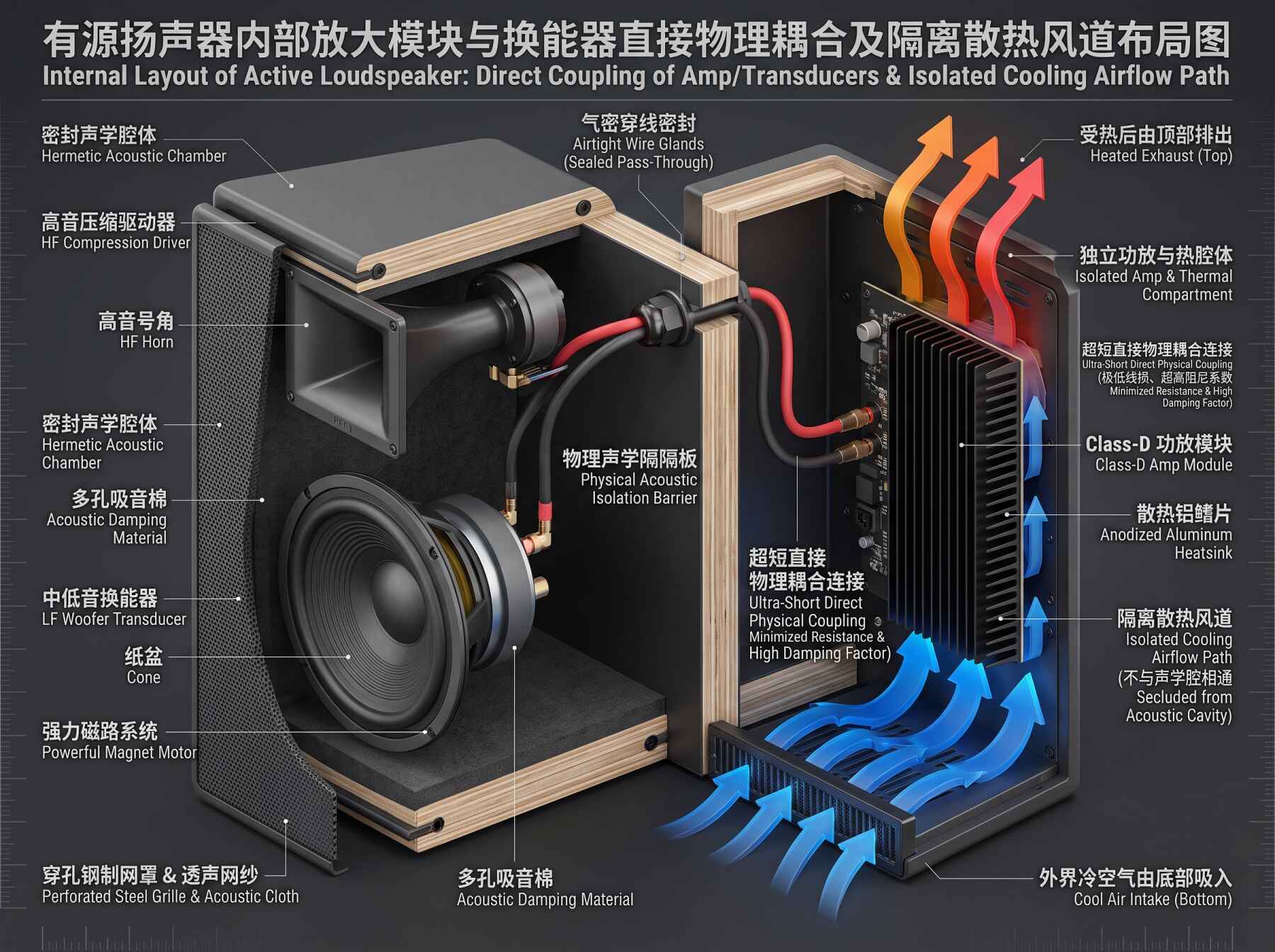
By integrating the amplifier module directly inside the loudspeaker enclosure, we eliminated the passive cable run between output stages and transducers. A 40-meter run of heavy copper speaker cable typically introduces roughly 0.35 ohms of loop resistance. When driving high-current subwoofers or heavy dual-12-inch drivers, this cable resistance crushes the damping factor down from over 1,000 at the amplifier chassis to less than 25 at the voice coil terminals, resulting in loose, sluggish low-end response and wasted thermal energy.
With the active architecture, the Class-D output stage sits less than 20 centimeters from the neodymium voice coils. Damping factor exceeds 1,200 right at the transducer terminals, giving the DSP absolute control over cone excursion and stopping transient overhang dead in its tracks.
| Distribution Tier | Signal / Input Stage | Processing & Conditioning | Amplification / Drive Stage | Physical Acoustic Transducer |
|---|---|---|---|---|
| Tier 1: Mains Distribution | Dual redundant 32A CEE Form Mains | Active PFC Regulation (85–265V) | Onboard Regulated SMPS Rails | Direct High-Current DC Rails |
| Tier 2: Ingestion & Control | Milan AVB / Analog Redundant Fallback | 96 kHz 64-bit Floating-Point DSP | Integrated Tri-Channel Class-D Stage | Zero-Cable-Loss Direct Coupling |
| Tier 3: Low-Frequency Drive | Ingested System Mix (45–350 Hz) | Linear-Phase FIR Bandpass & Dynamic Thermal Modeling | 1,500W RMS GaN Output Stage | Dual 12” Neodymium High-Excursion Woofers |
| Tier 4: High-Frequency Wavefront | Ingested System Mix (350 Hz–20 kHz) | Predictive Excursion Limiting & Phase Alignment | Dual 500W RMS PFFB Ultra-Low THD Stage | Coaxial High-Output Compression Drivers |
Pro Tips and Field Traps
- Beware the “Peak Music Power” Specification Game:
Never spec system headroom based on burst or 10-millisecond peak ratings. High-energy electronic music and modern live mixes possess high crest factors with long duty cycles. Ensure your Class-D modules specify sustained RMS power over a minimum of 200 ms to 1 second with all channels driven simultaneously. An amplifier that boasts 4,000W peak but throttles down to 400W continuous after two kick-drum beats will choke your low-end headroom. - Back-EMF and Reverse Rail Pumping:
When high-excursion subwoofers decelerate, the moving voice coil acts as an electrical generator, dumping back-electromotive force (Back-EMF) straight back into the amplifier’s output stage. In half-bridge Class-D designs, this energy can “pump” the power supply rails up to destructive voltage thresholds. Ensure your platforms utilize full-bridge (BTL) output topologies or intelligent energy-recycling power supplies that dissipate or recirculate regenerative energy without triggering over-voltage shutdown. - Generator Sizing and Phase Balance:
While Class-D with active PFC is incredibly efficient, running multiple high-density touring racks off field diesel generators requires careful attention. Poorly regulated generators with unstable governors can overshoot voltages when a touring rig transitions from full-throttle drop to silent acoustic break. Always maintain a 20% to 30% generator headroom margin, and balance active enclosures evenly across all three phases. - Acoustic Chamber vs. Electronics Isolation:
In active cabinet designs, never expose amplifier electronics and DSP boards to the internal acoustic chamber of a ported subwoofer or low-frequency enclosure. The intense internal air pressure (frequently exceeding 150 dB SPL inside the box) can physically vibrate surface-mount capacitors and inductors, inducing microphonic noise and mechanical fatigue. High-performance active speakers must always isolate amplifier modules within a sealed, externally heatsinked aluminum housing.
Industry Conclusion
The evolution of Class-D amplification is not merely an incremental story of lighter gear and reduced rack weight; it is a fundamental shift in how electrical energy is converted into acoustic pressure. By combining ultra-fast wide-bandgap semiconductors, closed-loop post-filter feedback, and direct transducer coupling, modern active systems achieve levels of sound pressure, transient agility, and thermal reliability that were unimaginable in the days of analog iron. As digital control architectures and power electronics continue to converge, the boundary between the amplifier and the loudspeaker has dissolved into a unified, high-precision acoustic instrument.