Introduction: The Heavy Iron Days Are Behind Us
If you spent any time loading amp racks onto touring trucks in the 1990s or early 2000s, your spine remembers the era of linear power supplies. A standard 12U touring rack loaded with three or four high-power Class AB or Class H amplifiers easily tipped the scales at well over 140 kg (300 lbs). The culprit was simple: massive copper-wound toroidal transformers and bank upon bank of heavy electrolytic reservoir capacitors.
Beyond the sheer physical toll on stagehands and transport logistics, the electrical footprint was brutal. At large outdoor festivals, sound crews routinely oversized diesel generator plants by a factor of three just to prevent voltage collapse during heavy low-end kick hits. In fixed installations like sports arenas and theatrical auditoriums, facility managers discovered that for every kilowatt of power pumped into the sound system, their mechanical HVAC systems consumed nearly an equivalent amount of power simply trying to pull that wasted thermal energy out of the rack rooms.
Today, the pro audio industry is deep into a quiet revolution. Driven by stringent international energy mandates, soaring touring freight costs, and the demand for higher channel densities in shrinking footprints, the transition to high-frequency Switch-Mode Power Supplies (SMPS) and regulated Class-D topologies is no longer a luxury. It is an engineering prerequisite.
Core Technical Analysis: Why SMPS and PFC Redefined Power Delivery
To understand why modern pro amplifiers run significantly cooler and lighter, we have to look past the audio amplification stage and inspect the power reservoir feeding it.
1. The Physics of the Transformer: Frequency vs. Mass
In a traditional linear power supply, the transformer operates at the line utility frequency (50 Hz or 60 Hz). According to Faraday’s law of induction:
$\mathcal{E} = -N \frac{d\Phi}{dt}$
The magnetic core cross-sectional area and the number of primary turns required to prevent core saturation are inversely proportional to operating frequency. At 50 Hz, transferring 3,000 to 5,000 Watts requires an enormous iron or silicon-steel core wrapped with thick copper wire.
SMPS sidesteps this by first rectifying the incoming 50/60 Hz AC line into a high-voltage DC bus, then chopping that DC voltage using high-speed MOSFETs or IGBTs at frequencies typically between 100 kHz and 250 kHz. Because the rate of change of magnetic flux ($d\Phi/dt$) is several thousand times higher at 150 kHz than at 50 Hz, the transformer core shrinks from the size of a bowling ball to the size of a coffee mug, using lightweight high-permeability ferrite materials.
| Architecture Characteristic | Legacy Linear Supply (50/60 Hz) | Basic SMPS (Unregulated / No PFC) | Advanced Regulated SMPS with Active PFC |
|---|---|---|---|
| Power Transformer Mass | 12 kg – 25 kg per unit | 0.8 kg – 1.8 kg per unit | 0.8 kg – 1.5 kg per unit |
| Operational Efficiency | 55% – 65% | 78% – 85% | 90% – 95% |
| Power Factor ($\cos \phi$) | ~0.70 – 0.75 | ~0.55 – 0.65 | >0.98 (near unity) |
| Mains Voltage Range | Fixed (e.g., 230V ±10% or 115V) | Narrow tolerance (tap switch required) | Universal (85V – 265V AC Auto-Sensing) |
| Rail Sag Under Heavy Load | Substantial (proportional to line sag) | Moderate | Negligible (actively regulated DC rails) |
2. Active Power Factor Correction (PFC): Stop Robbing the Grid
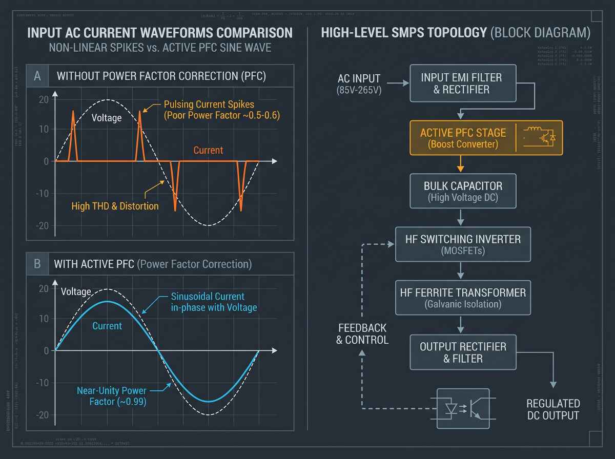
A switch-mode power supply alone does not solve all electrical problems. Standard rectifiers only draw current from the AC mains at the very peak of the voltage cycle when the line voltage exceeds the reservoir capacitor voltage. This creates narrow, high-amplitude spikes of current, producing a low Power Factor ($\text{PF} \approx 0.6$) and generating severe harmonic distortion on the mains line.
This is where Active Power Factor Correction becomes essential:
- Waveform Shaping: An active PFC circuit incorporates a high-speed boost converter between the input bridge rectifier and the main reservoir capacitors. It forces the input current to track the shape and phase of the AC input voltage sinusoidally.
- True Power Utilization: By achieving a Power Factor above 0.98, the apparent power ($\text{kVA}$) matches the real power ($\text{kW}$). This allows an amplifier to pull significantly more usable continuous and burst wattage from a standard 16A or 20A circuit breaker without nuisance tripping.
- Universal Voltage Regulation: Active PFC acts as a regulated pre-regulator. Whether the venue delivers clean 240V European mains, dirty 100V generator power in a rural festival, or suffers from severe mid-day voltage sags down to 90V, the internal DC rails stay pinned at their optimal design voltage.
3. Energy Recycling & Reactive Loudspeaker Loads
Loudspeakers are not simple non-inductive resistors; they are dynamic, complex reactive loads composed of voice coil inductance, suspension compliance, and back-electromotive force (Back-EMF). When a heavy 18-inch or 21-inch subwoofer cone decelerates after an explosive transient kick, its magnetic motor structure acts like a generator, pumping electrical energy back through the amplifier’s output terminals.
Legacy Class-AB amplifiers typically dissipated this reflected energy as wasted heat inside the output transistors. Modern high-efficiency Class-D stages coupled with bidirectional SMPS architectures can capture this back-EMF, recycling reactive energy back into the internal power supply reservoir capacitors rather than burning it off into the heatsink.
Field Application & Case Study: Touring Rig vs. Arena Retrofit
To put these figures into clear economic and operational perspective, let’s examine a real-world scenario: retrofitting an 8-rack, 32-channel system powering a medium-scale arena touring rig (16 dual 18-inch subwoofers and 16 high-output line array modules).
| System Metric | Legacy System (Class H + Linear Toroidal PSU) | Modernized System (EGT Audio PL-Series SMPS + Active PFC) | Net Engineering Improvement |
|---|---|---|---|
| Total Amplifiers | 16 units (2-channel, 3U each) | 8 units (4-channel, 2U each) | 67% Rack Space Reduction (48U down to 16U) |
| Total Amp Hardware Weight | ~560 kg (1,234 lbs) | ~96 kg (211 lbs) | -464 kg (-83% transport weight) |
| Average Thermal Output | ~14,200 BTU/hr (idle/nominal) | ~3,100 BTU/hr (nominal load) | 78% Reduction in Heat Generation |
| Mains Draw Peak (3-Phase 400V) | 3 × 38A (Current spikes, PF 0.65) | 3 × 14A (Balanced sinusoidal, PF 0.98) | Frees up generator headroom for lighting/video |
| HVAC Chiller Load in Facility | ~4.1 kW cooling capacity dedicated | ~0.9 kW cooling capacity dedicated | Substantial monthly facility utility savings |
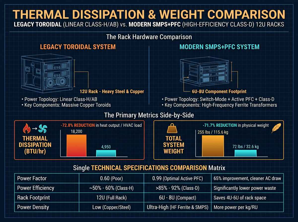
In touring logistics, shedding nearly half a metric ton of rack weight translates directly into reduced deadweight air freight, less fuel consumption per trucking mile, and faster two-man load-ins. In municipal installations—such as performing arts centers and sports stadiums running systems 14 hours a day—the dramatic drop in BTU heat rejection directly slashes monthly facility HVAC electricity bills.
Pro Tips and Field Traps (“Gotchas”)
While modern SMPS technology is remarkably robust, transitioning to high-frequency, high-efficiency topologies presents unique engineering challenges that field engineers and system designers must watch out for:
1. The Triplen Harmonic Trap on Three-Phase Neutrals
- The Trap: When running older non-PFC switch-mode power supplies across a standard three-phase electrical distribution (Wye configuration), the 3rd, 9th, and 15th harmonic currents (triplen harmonics) do not cancel out in the neutral conductor. Instead, they sum constructively.
- The Field Consequence: You might measure a safe 18A on Phase A, Phase B, and Phase C, yet find 28A overheating your undersized neutral wire!
- The Fix: Ensure all high-density amp racks utilize amplifiers equipped with Active PFC. Alternatively, oversize your neutral cable to 150%–200% of the phase conductors when working with uncorrected legacy switchers.
2. Sizing Generators for SMPS Peak Crest Factors
- The Trap: Audio signals are highly dynamic, exhibiting crest factors typically between 6 dB and 14 dB (peak-to-average power ratios). A sound engineer might calculate that their modern SMPS amp rack only draws an average of 4 kW and decide a small 8 kVA generator is sufficient.
- The Field Consequence: When the 35 Hz sub drop hits, the sudden high-current transient demand causes the generator’s Automatic Voltage Regulator (AVR) to hunt or dip. If the AVR overreacts, it can trigger an overvoltage surge that damages sensitive digital consoles or DSP units.
- The Fix: Size your generators based on peak transient demand rather than average continuous draw. Even with PFC, maintain a safety headroom multiplier of at least 1.8x to 2.2x over the total dynamic audio load.
3. Subwoofer “Breathing” and Rail Sag in Cheap SMPS Designs
- The Trap: Not all SMPS circuits are engineered equally. In low-cost designs, manufacturers minimize the secondary capacitor bank to save pennies, relying purely on the switching regulator to pump current on demand.
- The Field Consequence: High-frequency switching supplies can respond quickly, but continuous sub-bass notes (such as synth drones or extended 808 kicks in electronic music) require massive localized charge reservoirs. An under-capacitanced SMPS will suffer DC rail collapse during sustained low frequencies, causing audible dynamic compression and lifeless bass impact.
- The Fix: Select professional touring-grade power supplies designed with multi-stage resonant topologies and generous secondary energy storage buffers—such as the power architectures deployed in EGT Audio’s PL-Series, which sustain continuous dynamic bursts without audio rail collapse.
Industry Conclusion: Green Engineering as a Performance Multiplier
The pro audio industry’s shift toward switch-mode power supplies and green amplification isn’t just about environmental compliance or green corporate messaging—it is fundamentally superior audio engineering.
By pushing power conversion frequencies into the hundreds of kilohertz and implementing active, intelligent power factor correction, we have decoupled raw output power from physical iron weight. The result is a new generation of touring and installation systems that hit harder, run cooler, draw less current from overloaded mains grids, and dramatically lower the operating costs of venues worldwide.
In modern system design, high efficiency is no longer a compromise on headroom; it is the very reason headroom exists.