Introduction: The “Line Array Everything” Trap
Walk into half the newly renovated municipal auditoriums or university theaters built in the last five years, and you will see the exact same mistake hanging from the proscenium truss: a massive, 8-box dual-10-inch line array hung in a shallow, 350-seat room with a 6-meter ceiling and untamed plaster walls. The contractor sold the client on “tour-grade line array technology,” hung the boxes, ran an auto-EQ sweep, and walked away.
The result? The first three rows are getting blasted in the knees by the bottom cabinet, the rear wall is reflecting a wall of low-mid mud back onto the stage microphones, and the VIP seats tucked under the deep balcony overhang sound like they are listening to the show through a heavy wool blanket.
In theater and auditorium integration, there is no single loudspeaker topology that solves every geometric problem. True acoustic coverage in complex multi-tiered rooms requires a hybrid strategy: combining the long-throw cylindrical wave control of compact line arrays with the surgical, phase-coherent dispersion of point source and coaxial loudspeakers, all tied together through an intelligent DSP matrix.
Core Technical Analysis: Spherical vs. Cylindrical Wavefronts in Enclosed Spaces
To build an effective selection matrix, we first have to respect how sound energy decays over distance and interacts with room boundaries.
1. Point Source Loudspeakers (Spherical Propagation)
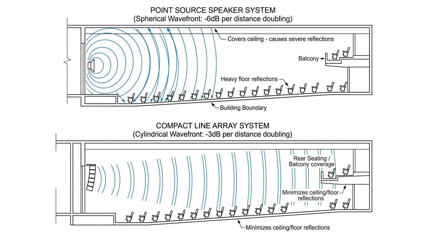
A traditional point source enclosure radiates sound as an expanding sphere (governed by the inverse-square law). For every doubling of distance in a free field, your Sound Pressure Level (SPL) drops by 6 dB.
- Where they win: Short-to-medium throw distances (under 15–18 meters), wide vertical dispersion needs (such as steep stadium-style raked seating), and localized zone fills where you want rapid acoustic falloff so energy doesn’t bleed into adjacent zones.
- Where they fail: In a 30-meter-deep auditorium, if you need 95 dB at the back wall, a single point source hang near the stage has to push roughly 113–115 dB at 2 meters. You will tear the ears off the front rows just to make the back row hear the presenter.
2. Compact Line Arrays (Cylindrical Propagation)
When multiple line array elements are coupled vertically with inter-driver spacing smaller than half the wavelength of the operating frequency, their wavefronts sum into a cylindrical wave in the near-to-mid field. Instead of expanding vertically and horizontally, energy is constrained on the vertical plane—dropping by only 3 dB per doubling of distance until it transitions to spherical propagation at the far boundary (the transition distance).
- Where they win: Long-throw rooms (20+ meters), rooms with highly reflective ceilings and floors (since narrow 10° nominal vertical splay per cabinet keeps energy off the ceiling), and raked orchestra floors where progressive J-shading lets you allocate more energy to the rear seats than the front seats.
- Where they fail: Ultra-short throws, rooms with low trim heights where you cannot hang at least 4 to 6 cabinets (an “array” of two boxes is not a line array; it is just a very expensive, vertically confused point source), and deep under-balcony cavities obstructed by structural concrete soffits.
The Theater & Auditorium Selection Matrix
Before opening EASE or CAD software, system integrators can use the following architectural matrix to determine whether a zone calls for a primary point source, a compact line array, or a hybrid matrix combination.
| Venue Geometry & Acoustic Profile | Throw Distance | Primary Main PA Selection | Secondary Fill / Delay Requirement | Key Acoustic Risk to Manage |
|---|---|---|---|---|
| Intimate Lecture Hall / Black Box Theater (200–350 seats, flat or mild rake, ceiling < 6m) | 10m – 16m | 12” or 15” 2-Way Point Source (L/C/R or L/R flown high with down-tilt) | Coaxial Stage Lip Front Fills (if stage is > 10m wide) | Early ceiling reflections and stage mic feedback from wide vertical horn dispersion. |
| Medium Multi-Purpose Auditorium (400–800 seats, single deep balcony, ceiling 8m–10m) | 18m – 28m | Dual 6.5” or Dual 8” Compact Line Array (4–6 boxes per side) | Point Source Under-Balcony Delays + Coaxial Front Fills | Acoustic shadow under the balcony soffit; comb filtering in the transition zone between Main PA and delays. |
| Grand Performing Arts Theater (900–1,500+ seats, double balcony, orchestra pit) | 28m – 42m+ | Dual 10” Compact Line Array (6–10 boxes per side, active bi-amped or DSP-driven) | Upper Balcony Point Source Delays + Under-Balcony Delays + Center Cluster | High-frequency air absorption over 30m; low-mid build-up on stage from coupled array woofers. |
Field Application & Case Study: Matrixing a 750-Seat Tiered Auditorium
Let’s look at how these principles come together on an actual job site. Last year, our engineering team consulted on a 750-seat municipal cultural center auditorium. The room measured 26 meters deep by 20 meters wide, featuring an orchestra floor, a deep balcony overhang starting at 18 meters from the stage lip (with only 2.6 meters of clearance underneath), and a reverberation time ($RT_{60}$) hovering around 1.3 seconds at 1 kHz.
Hanging a massive dual-12-inch concert rig would have visually blocked the stage lighting grid and overloaded the room’s acoustic volume. Instead, we deployed a 4-Zone Hybrid Matrix Architecture combining compact line array hangs with targeted point source and coaxial enclosures.
1. Main Left/Right FOH Hang: High-Impedance Compact Line Array
To cover the main orchestra seating from row 4 back to the 18-meter balcony face—plus the upper balcony seating—we specified 6 units per side of the EGT GL208 (dual 8-inch, 2-way passive line array modules) paired with a flown GL15S 15-inch subwoofer at the top of each hang.
Why it worked: Each GL208 cabinet features a tight $70^\circ \times 10^\circ$ dispersion pattern and weighs just 22 kg, keeping the structural load well within the theater’s existing proscenium I-beam rating. By setting the top three boxes at $1^\circ$ to $2^\circ$ inter-cabinet splay angles, we projected clean, phase-coherent energy straight to the upper balcony without splashing off the decorative plaster ceiling.
The 16-Ohm Advantage: Because the GL Series utilizes a 16-ohm nominal impedance design, we linked 4 cabinets in parallel per amplifier channel to present a stable 4-ohm load. Alternatively, in theaters where rack space is nonexistent, substituting the GL15S-DSP active subwoofer (which houses a 2x800W @ 8$\Omega$ Class-D amplifier withPFC and 24-bit/48kHz DSP) allows the sub’s secondary amplifier channel to directly power 4 passive GL208 tops right from the air.
2. Stage Lip Front Fills: Ultra-Compact Coaxial Point Sources
Because our main GL208 arrays were flown 5.5 meters apart on the proscenium walls, the center seats in rows 1 through 3 sat inside a classic “V-shaped” high-frequency dead zone. Furthermore, if listeners in the front row only hear the main array hanging 6 meters above their heads, their brains localize the actor’s voice to the ceiling rather than the stage.
- The Fix: We recessed 4 units of the EGT C05 across the front stage apron. The C05 is a 5.5-inch 2-way coaxial multipurpose point source housed in a tiny $200 \times 200 \times 200\text{ mm}$ birch plywood cube weighing just 4.5 kg. Because the 38.5mm HF voice coil is mounted coaxially at the acoustic center of the 5.5-inch woofer, there is zero off-axis lobing at close range, pulling the vocal image right down to the performer’s mouth.
3. Under-Balcony Delay Ring: Controlled Coaxial Point Sources
At the 18-meter mark, the concrete balcony fascia physically blocked the top two-thirds of the main line array from reaching the back six rows of the orchestra floor.
- The Fix: We mounted 4 units of the EGT FX-8 (8-inch 2-way coaxial loudspeakers, 114 dB Max SPL) using low-profile U-brackets along the underside of the balcony soffit. Using a coaxial point source here ensures smooth conical coverage across the low-ceilinged pocket without bulky horn flares obstructing sightlines.
4. Signal Routing & Amplification Matrix Topology
To make these disparate speaker types behave as a single unified acoustic source, every enclosure group must be fed by dedicated DSP matrix outputs with independent delay, crossover, and shading filters:
| DSP Matrix Output Channel | Target Acoustic Zone | Loudspeaker Model & Qty | Amplifier Pairing | Key DSP Processing Parameters |
|---|---|---|---|---|
| Matrix Out 1 & 2 | Main L/R FOH Array | EGT GL208 (6 per side) | EGT AK4800 (Ch 1–4 @ 4$\Omega$) | 90 Hz LR24 HPF; HF air-loss shelf (+2.5 dB > 10 kHz) |
| Matrix Out 3 & 4 | Main L/R Subs | EGT GL15S (1 per side) | EGT AK4600 (Bridged/Stereo) | 42 Hz BW18 HPF to 90 Hz LR24 LPF; phase aligned to GL208 |
| Matrix Out 5 | Center Front Fills | EGT C05 (4 units spaced) | EGT AK4400 (Ch 1–2) | 150 Hz LR24 HPF; +6.5 ms Delay; -4 dB level shading |
| Matrix Out 6 & 7 | Under-Balcony Delays | EGT FX-8 (4 units) | EGT AK4400 (Ch 3–4) | 110 Hz LR24 HPF; +64.2 ms Delay (Haas +12 ms offset) |
Pro Tips & Field Traps: Where Integrators Get Burned
Even with the right loudspeaker selection matrix, three commissioning mistakes regularly ruin theater installations:
1. Forgetting the Haas Effect (Precedence Effect) on Delays and Front Fills
If you take a laser disto, measure 18.5 meters from the main line array to the under-balcony delay speaker, divide by the speed of sound ($343\text{ m/s}$), and type 53.9 ms into your DSP delay block, you just made a classic rookie mistake. If the delay speaker and the main PA arrive at the listener’s ear at the exact same millisecond, the listener will localize the sound directly to the smallFX-8 speaker bolted 2 meters above their head.
- Field Rule: Always add 10 ms to 15 ms of extra “Haas offset” delay beyond the acoustic arrival time of the main array. Thanks to the Precedence Effect, the human brain locks onto the first arriving wavefront (from the stage/main PA) for directional localization, while using the delayed speaker (arriving 12 ms later) purely to restore high-frequency speech intelligibility and SPL.
2. Running Full-Range Energy into Under-Balcony Delays
Low frequencies below 200 Hz have long wavelengths that diffract effortlessly around the balcony fascia and flood into the under-balcony zone from the main PA. What gets blocked by the balcony is the 2 kHz to 12 kHz consonant band. If you run your under-balcony point sources full-range down to 60 Hz, their low-mid output will collide with the main PA’s low-mids, turning the back of the room into a boomy soup. High-pass your under-balcony fills aggressively—typically between 110 Hz and 140 Hz—and treat them strictly as mid-high clarity restorers.
3. Under-Damping Amplifier Selection on Long Cable Runs
In theaters, amplifier racks are often tucked into a basement dimmer room 40 meters away from the proscenium hang. Long runs of under-sized copper cable destroy your effective damping factor, leading to sluggish low-mid transient response. When driving passive point sources and line arrays over distance, use 10 AWG or 12 AWG OFC cable and pair them with high-damping-factor Class-H or Class-D power amplifiers—such as the EGT AK Series (featuring a damping factor $>230$ at $8\Omega$ and toroidal linear power stability) or the ET Series (damping factor $>800$ at $1\text{ kHz}/8\Omega$)—to keep cone excursion tightly controlled during dynamic theatrical peaks.
Industry Conclusion
Designing a theater or auditorium sound system is an exercise in acoustic restraint. A compact line array gives you the reach and vertical boundary control to conquer long throws and reflective ceilings, while point source and coaxial enclosures give you the surgical brush strokes needed to fill the stage lip and under-balcony shadows. By mapping your venue geometry into a clear selection matrix and aligning each zone in time and frequency, you ensure that every patron—from the front row donor seat to the back corner under the balcony—experiences the exact same vocal intimacy and dynamic impact.